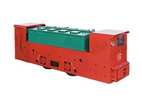
Principle And Selection Of Mining Electric Locomotive
Date:2020-02-13 Label:
Electric Locomotive
Underground Mining Locomotive
Locomotive
Principle and type selection of mining electric locomotive system. Structural principle of the transformation. The DC excitation of the synchronous motor is provided with a fully digital DC speed regulator (Siemens 6RA70 rectifier). The 6RA70 rectifier is used as the DC excitation power source of the synchronous motor. The automatic input is to detect the change of the rotor slip of the synchronous motor through the slip detection link, and feedback the detection signal to the S7 300 PLC. Finally, the PLC sends commands to control the 6RA70 to realize the Automatic control of DC excitation power.
Hardware and software selection
1) Selection of hardware mining electric locomotive equipment According to the specific parameters of the excitation voltage / current (140 V / 270 A) of the ball mill synchronous motor, the S IMOREG DC M aster with the model D420 / 400 M req GeGF6V 62 (output 400 V / 400 A) is selected. The 6RA70 rectifier acts as an excitation drive. The PLC selects Siemens S7 300PLC (CPU 315 2DP) of small and medium control scale as the DP master station for the automatic control of 32 ball mills. It controls the armature output of the 6RA70 (that is, the excitation input of the synchronous motor) through the DP bus, and simultaneously collects the 6RA70 The feedback information is sent to the host PC and monitored in real time in HM I.
2) Software selection STEP7 (V5 3): It is used for the management of hardware and software of the automation system controlled by SIMAT IC S7 300/400 PLC, which can realize the hardware configuration, parameter setting, communication configuration, programming test, operation of PLC Monitoring and diagnosis and maintenance functions; W inCC (V60): Siemens Windows Control Center, for development and design software for human-machine interface (HM I); DriveM on iter: Siemens drive control software, for parameter setting and 6RA70 monitor. Digital transformation analysis Introduction to the working principle of each component unit of the ball mill synchronous motor excitation system.
1) Transformer: Reduce the stator power 6 kV high-voltage bus to 400 V as the power source of the rectifier, and at the same time, it can feed back the reactive power compensation of the synchronous motor to the primary side of the power grid, thereby increasing the power factor of the 6 kV bus.
2) Automatic demagnetization link: As the synchronous machine starts the stator winding or full voltage asynchronous start, the rotor winding will generate a large induced electromotive force, so the rotor demagnetization circuit must be designed to ensure that the normal starting torque is reached at the same time. The effect of automatic rotor demagnetization.
3) Slip detection link: As shown, during the asynchronous starting of the synchronous motor, the induced voltage of the rotor circuit is a sine wave with a frequency decaying from 50 Hz to 0 H z, and the frequency of the rotor voltage in a certain period (f 2) Corresponds to the slip rate (S) of the motor during this period.
